As construction projects grow in complexity, so too do the demands of lifting operations. At Amrose Associates, we specialise in designing tailored lifting solutions that meet challenging requirements around weight, space, and safety. Our mechanical and structural engineers work closely with project teams to manage risks, avoid delays, and keep operations running smoothly.
Here are a few recent examples of how we’ve helped deliver complex lifts with confidence.
Tower crane tie floor brackets
This project in Greenwich, London, is a prime example of our work with tower crane ties, which connect the crane to buildings during construction to provide stability & lateral restraint to the crane.

Connections are often made to building core walls. In this case, the site’s geometry meant the ties had to be fixed to the structure via the floor slabs.
Amrose provided design checks to the steel brackets, which had been modified to suit increased tie loads for the floor arrangement, and Cat 3 finite element analysis checks for the building’s concrete floor slabs.

Pressure Equipment Lifting Brackets
On this project, Amrose Associates designed 3 pairs of lifting lugs to lift pressure equipment on a UK refinery site. We used the existing holes on the flanges of the components and bespoke lugs were designed and fabricated to match the curvature of the lifted components. These comprised an upper and lower assembly to ensure the pitch of the combined lifting assembly perfectly matched the thickness of the lifted flanges.

Load factors were considered in accordance with British Standards for detachable load lifting attachments, ensuring that there was sufficient structural strength for the dynamic loads associated with lifting.
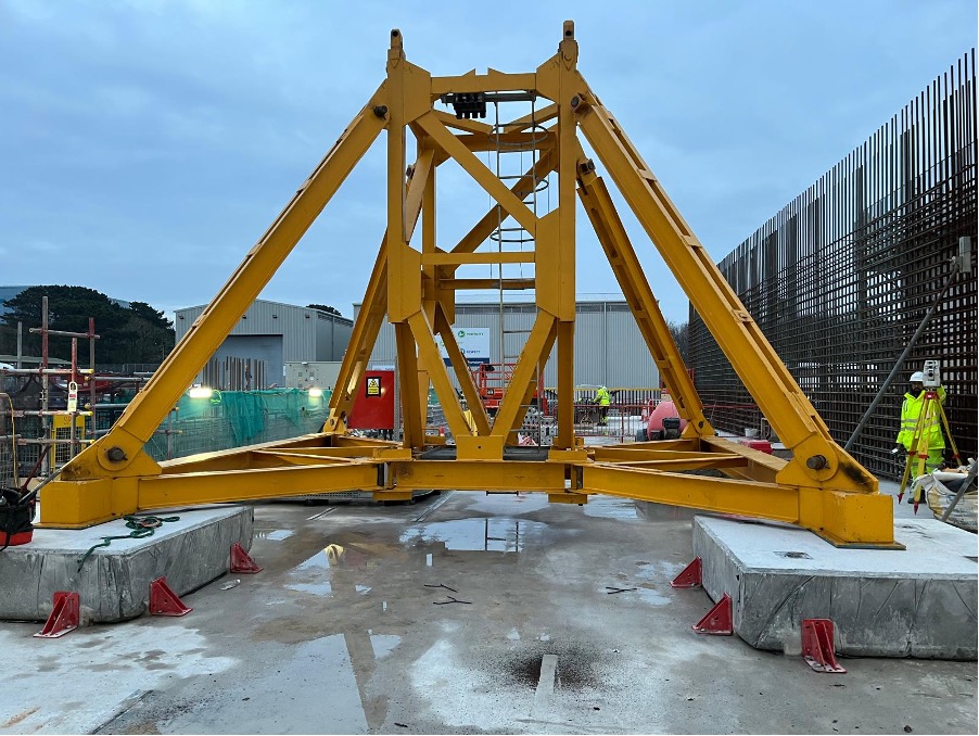
Recycled steel for tower crane load testing bed
On this project we were commissioned to design a steel frame which would be used as a ballast lifting bed for load tests on the client’s tower cranes.

We were able to reuse recycled steel sections from other projects to build the load testing bed. The lifting bed frame is lifted by 4 lifting eyes connecting to a central lifting point above. This maintains a maximum included angle between the chains of 30°.

Removable foundation details for crane stability
We have been working at Hinkley Point C to engineer a temporary foundation for a ballasted tower crane. Foundation details for this type of crane typically take the form of a concrete raft, or multiple individual concrete plinths for each crane leg. The crane kentledge meant there was no need to vertically fix to the foundation. The crane still needed to be fixed to the foundations with anti-rotation studs, however, to resist lateral loads such as wind loading and the crane’s torsional moment during operation.

In this particular case, we were mindful of the fact that the foundations had to be removable when the crane was no longer in use.
The Amrose engineering team designed a solution that ensured sufficient foundation depth and reinforcement to spread the crane loads and reduce the bearing pressure on the permanent slab and soil strata below. The foundation size was also checked to ensure that the anti-rotation studs joining the crane to the footings had enough concrete volume to connect to and provide sufficient strength.

A visqueen layer at the base of the foundation created a separation between the concrete pours, and lifting anchors were cast into the footing; both of these details facilitate the foundation removal at the end of the crane works, minimising the risk of damage to the permanent slab below.

Our experience in tower crane foundation design of this kind helped us understand how friction could be taken into account for resisting horizontal loads at the base of the footings. Given the site complexity and approach to risk management, Amrose opted to use 90-degree brackets fixed to the slab to provide lateral restraint. These were the same type that were used for the formwork for casting the plinths, which meant they could be reused on site for lower costs and lower embodied carbon in construction.
During this project, the site team picked up on an installation error, which resulted in the lower portion of the plinth being curved and reduced in size. We quickly undertook structural verifications to make sure adequate footing strength was still achieved with the ‘as-built’ geometry. We proposed a remedial detail at the lateral restraints so that they and the fixings wouldn’t be overstressed. This ongoing complex engineering support is typical of our partnership approach and shows the real value we can add during an evolving project.
The initial calculations assume that all specifications remain the same throughout construction. Anyone who has worked on a complex building scheme will tell you that this is rarely the case! Continual monitoring, surveying and recalculation is an essential part of our role on a living and breathing project.
Customisation and collaboration
These projects demonstrate that successful lifting operations depend on both technical expertise and collaboration. Our engineers work closely with clients, contractors, and stakeholders so that we fully understand each project’s objectives and constraints. This collaborative approach allows us to deliver solutions that are not only technically sound but also aligned with the overarching goals of the project.
By choosing Amrose Associates as your engineering partner, you can be confident in the safety, efficiency, and success of your lifting operations.
For more information on our services or to discuss your project needs, please contact us at enquiries@amroseassociates.com or call 0113 391 9840.